Are You Embarrassed By Your MULTIPLEXER AND DEMULTIPLEXER understanding?
-Understanding MUX and DEMUX in Digital Logic

I'm a Tech passionate who is in the chase of awesome projects and interesting tech concepts. I wish to create an impact in the field of computer science.
🔵Introduction
➜A multiplexer is a circuit that accepts multiple inputs but outputs only one. A demultiplexer works just like a multiplexer in reverse, accepting only one input and producing several outputs. Multiplexers and demultiplexers are commonly used together in various communication systems.
🔵Multiplexer
🔸Multiplexer means many into one. A multiplexer is a circuit used to select and route any one of the several input signals to a single output. Multiplexers are switches that are commonly utilised in electronic circuits. High-speed circuits, on the other hand, necessitate automatic multiplexer selection. A mechanical switch is incapable of performing this task effectively. As a result, multiplexers are made of electronic components and are utilised to accomplish high-speed switching.
🔸Multiplexers may process two types of data: analogue and digital. Multiplexers for analogue applications are made with relays and transistor switches. They are constructed from ordinary logic gates for digital applications.
🔸A digital multiplexer, sometimes known as a digital multiplexer, is a circuit having several inputs but only one output. We can direct any input to the output by using Selection lines. Multiplexers that are commonly used include 2-to-1, 4-to-1, 8-to-1, and 16-to-1 multiplexers.
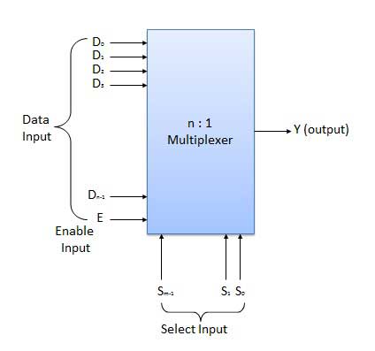
🔸The diagram below depicts the overall concept of a multiplexer with n input signals, m control signals, and one output signal.
🟢Understanding 4-to-1 Multiplexer
🔹Four input bits, two control or select bits, and one output bit comprise the 4-to-1 multiplexer. D0, D1, D2 and D3 are the four input bits. Only one of these is sent to output Y. The output is determined by the values of the control inputs A and B. The control input selects which data bit from the input is sent to the output.
🔹For example, when A B = 0 0, the higher AND gate is activated, while the other AND gates are disabled. As a result, data bit D0 is sent to the output, yielding Y = D0.

🔹If the control input is changed to A B = 1 1 , all gates are disabled except the bottom AND gate. In this case, D3 is transmitted to the output and Y = D3.
🟢Applications of Multiplexer
🔸Telephone Network – Multiple audio signals are combined on a single line for transmission in a telephone network using multiplexers. Multiple audio signals can be isolated in this manner, and the desired audio signals will finally reach their intended listeners.
🔸Communication System – A communication system is a collection of systems that allow communication to take place, such as a transmission system, a relay and tributary station, and a communication network. Using a multiplexer, the efficiency of a communication system can be significantly boosted. Multiplexers enable the simultaneous transmission of multiple types of data, such as audio and video, over a single transmission line.
🔸Computer Memory – Multiplexers are used in computers to implement large amounts of memory while reducing the number of copper lines required to connect the memory to other sections of the computer circuit.
🔸Transmission from the Computer System of a Satellite – Using GPS (Global Positioning System) satellites, a multiplexer can be utilised to transmit data signals from the computer system of a satellite or spacecraft to the ground system.
🔵Demultiplexer
Demultiplexer means one to many. A demultiplexer is a circuit with one input and many outputs. By applying a control signal, we can steer any input to the output. A few types of demultiplexers are 1-to-2, 1-to-4, 1-to-8 and 1-to-16 demultiplexers.

🟢Understanding 1-to-4 Demultiplexer
The 1-to-4 demultiplexer has 1 input bit, 2 control or selection bits, and 4 output bits.

🔹The input bit is designated as Data D. This data bit is sent to the selected output lines, which are determined by the values of A and B, also known as the control or Select Inputs.
🔹When A B = 0 1, the second AND gate from the top is turned on, while the other AND gates are turned off. As a result, data bit D is transferred to the output Y1, resulting in Y1 = Data.
🔹Y1 is LOW if D is LOW. Y1 is HIGH if D is HIGH. The value of Y1 is determined by the value of D. All other outputs are at a low level.
🔹If the control input is modified to A B = 1 0, all gates save the third AND gate from the top are disabled. Then D is only sent to the Y2 output, and Y2 = Data.
🟢Applications of Demultiplexer
🔹A demultiplexer is a device that connects one source to multiple destinations. The principal application area of a demultiplexer is communication systems that utilise multiplexers. The majority of communication systems are bidirectional, meaning they work in both directions (transmitting and receiving signals). As a result, for the majority of applications, the multiplexer and demultiplexer operate in tandem. Demultiplexers are also used to rebuild parallel data and ALU circuits.
🔹Communication System – Multiplexers are used in communication systems to transfer several data types such as audio, video, and other types of data over a single transmission line. This procedure facilitates transmission. At the receiving end, the demultiplexer receives the multiplexer's output signals and converts them back to the original form of the data. In a communication system, the multiplexer and demultiplexer work together to carry out the process of data transmission and receiving.
🔹ALU (Arithmetic Logic Unit) – The output of an ALU circuit can be stored in several registers or storage units using a demultiplexer. The ALU output is delivered into the demultiplexer as the data input. Each demultiplexer output is coupled to multiple registers, which can store data.
🔹Serial to Parallel Converter – In order to rebuild parallel data from an incoming serial data stream, a serial to parallel converter is used. Serial data from the incoming serial data stream is sent as data input to the demultiplexer at regular intervals in this technique. A counter is connected to the demultiplexer's control input. This counter guides the data signal to the demultiplexer's output, where it is stored. After all data signals have been stored, the demultiplexer output can be recovered and read out in parallel.
Thank you So much for reading😊. Hope I could add some value.
Written with heart by - MITHIN DEV
All representations belong to respective creators.
![[01] What is a Simple Game Engine?](/_next/image?url=https%3A%2F%2Fcdn.hashnode.com%2Fres%2Fhashnode%2Fimage%2Fupload%2Fv1679619224671%2Fde6bc474-4a14-4274-968b-6e3dc4d8e4e1.jpeg&w=3840&q=75)


