

MULTIPLEXER IN DIGITAL LOGIC? It's Easy If You Do It Smart
-Multiplexer (MUX) and Multiplexing


🟢What is Multiplexing?
🔹Multiplexing means many to one.
🔹The technique of mixing one or more signals and broadcasting them on a single channel is known as multiplexing. In analogue communication systems, a communication channel is a limited resource that must be used wisely. Multiplexing is a very important idea for cost-effective and efficient channel use since it allows several users to share a single channel in a logical fashion.
🔹The three common types of Multiplexing approaches are:
Time
Frequency
Space
🔹The landline telephone network and cable television are two of the best examples of Multiplexing Systems in use in our daily lives.
🔹A multiplexer is a device that is in charge of multiplexing. Analog and digital signals are both routed through multiplexers. A multiplexer is the most often used combinational circuit and an essential component in many digital systems.
🔹These are typically used to create a predetermined path between several sources and a single destination. A fundamental multiplexer has numerous data input lines and a single output line. Many digital system applications use these, including data selection and routing, logic function generators, digital counters with multiplexed displays, telephone networks, communication systems, waveform generators, and so on. This article will go over many types of multiplexers and their designs.
🟢What is a Multiplexer?
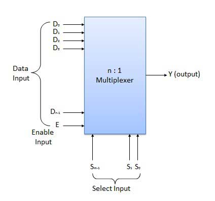
🔹A multiplexer, often known as a data selector, is a digital switch. It is a Combinational Logic Circuit having multiple input lines, multiple output lines, and multiple select lines. It receives binary data from several input lines or sources and routes a specific input line to a single output line based on a set of chosen lines.
🔹When the enable switch is turned on, data from numerous sources is routed to a single output line, as indicated in the image below. As a result, multiplexers are often known as "many-to-one" combinational circuits.
🔹If there are m selection lines in a multiplexer, then the number of possible input lines is 2m. Alternatively, we can say that if the number of input lines is equal to 2m, then m selection lines are required to select one of n (consider 2m = n) input lines.
🔹The number of data inputs to a multiplexer is often a power of two, such as 2, 4, 8, 16, and so on. Multiplexers that are commonly used include 2-to-1, 4-to-1, 8-to-1, and 16-to-1 multiplexers.
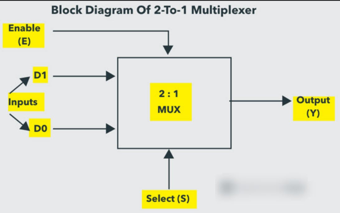
🟢2-to-1 Multiplexer
🔹Two inputs D0 and D1, one select input S, and one output Y make up a 2-to-1 multiplexer. The output is connected to either of the inputs depending on the selected signal. Because there are two input signals, there are only two ways to connect the inputs to the outputs, so one choice is required to perform these actions.
🔹If the chosen line is low, the output is switched to the D0 input; if the select line is high, the output is switched to the D1 input.
🔹The 2-to-1 multiplexer's truth table is illustrated below. The inputs D0 and D1 are produced at outputs based on the value of the chosen input. When the Select value is 0, the output is D0; when the Select value is 1, the output is D1.
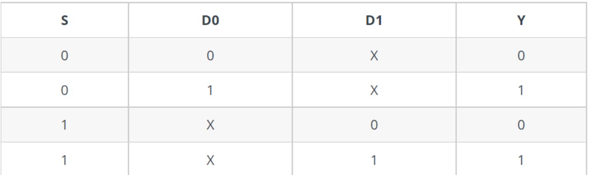
🔹The 'X' in the truth table above represents a don't care situation. So, ignoring the don't care situations, the Boolean Expression of a conventional 2-to-1 Multiplexer is: Y = S'D0 + SD1
🔹The logic circuit of a 2-to-1 multiplexer can be created using logic gates employing the above output expression, as shown in the figure. There are two AND gates, one NOT gate, and one OR gate. When the select line, S=0, the lower AND gate output is zero, but the higher AND gate output is D0. As a result, the OR gate's output is equal to D0.
🔹Similarly, when S=1, the upper AND gate output is zero, but the lower AND gate output is D1. As a result, the OR gate's output is D1. As a result, the above-mentioned Boolean equation is satisfied by this circuit.

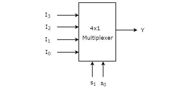
🟢4-to-1 Multiplexer
🔹A 4-to-1 multiplexer consists of four data input lines as D0 to D3, two select lines as S0 and S1 and a single output line Y. The select lines S0 and S1 select one of the four input lines to connect the output line. The multiplexer decodes the input through a select line.
🔹The truth table of a 4-to-1 multiplexer is shown below.
🔹From the above truth table, we can write the output expressions as follows:
✔Y = S0' S1' D0 + S0' S1 D1 + S0 S1' D2 + S0 S1 D3
🔹A 4-to-1 multiplexer can be created using basic logic gates based on the output equation above. The logic circuit of a 4:1 MUX is shown below, which is constructed using four 3-input AND gates, two 1-input NOT gates, and one 4-input OR gate.
🔹Each data input line is connected as an input to an AND gate in this circuit, and two select lines are connected as the other two inputs. In addition, there is an Enable signal. To produce the output Y, the outputs of all the AND gates are connected to the inputs of the OR gate.

🟢8-to-1 Multiplexer
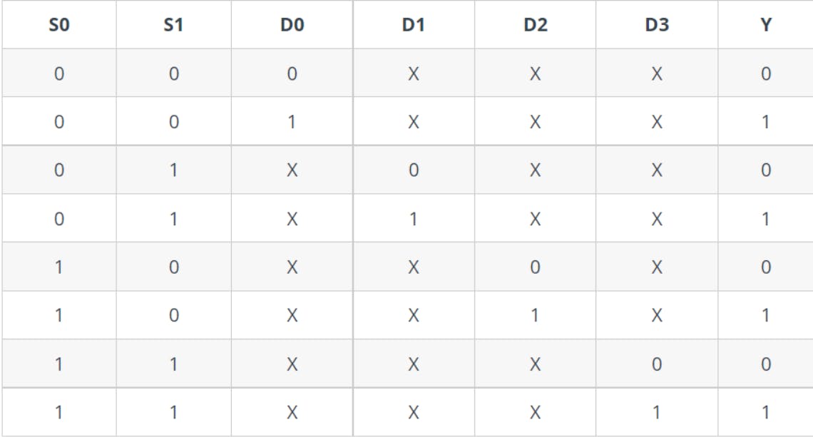
🔹An 8-to-1 multiplexer consists of eight data inputs, three input select lines and a single output line Y. Depending on the select line combinations, the multiplexer selects the inputs.

🔹The truth table for an 8-to1 multiplexer is given below with eight combinations of inputs so as to generate each output corresponding to the input.

🔹From the above truth table, the Boolean equation for the output is given as:
🔹Y = S0' S1' S2' D0 + S0' S1' S2 D1 + S0' S1 S2' D2 + S0' S1 S2 D3 + S0 S1' S2' D4 + S0 S1' S2 D5 + S0 S1 S2' D6 + S0 S1 S2 D7
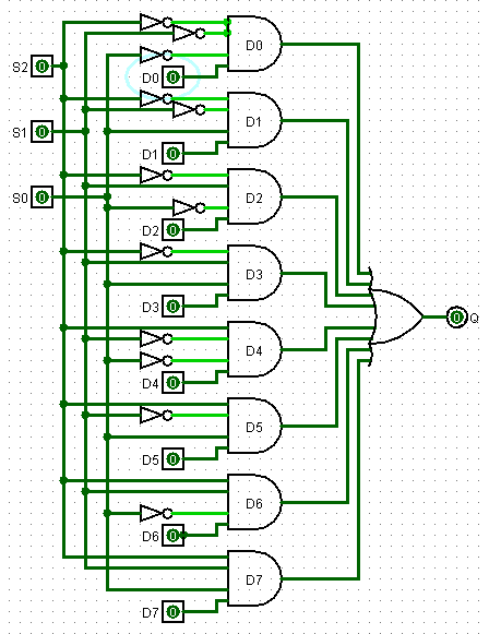
🔹From the above Boolean equation, the logic circuit diagram of an 8-to-1 multiplexer can be implemented by using 8 AND gates, 1 OR gate and 7 NOT gates as shown in the below figure. In the circuit, when enable pin is set to one, the multiplexer will be disabled and if it is zero, then select lines will select the corresponding data input to pass through the output.
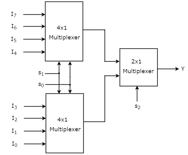
🟢8-to-1 Mux using 4-to-1 Mux and 2-to-1 Mux
🔹An 8-to-1 MUX can be made using two 4-to-1 MUX and one 2-to-1 MUX.
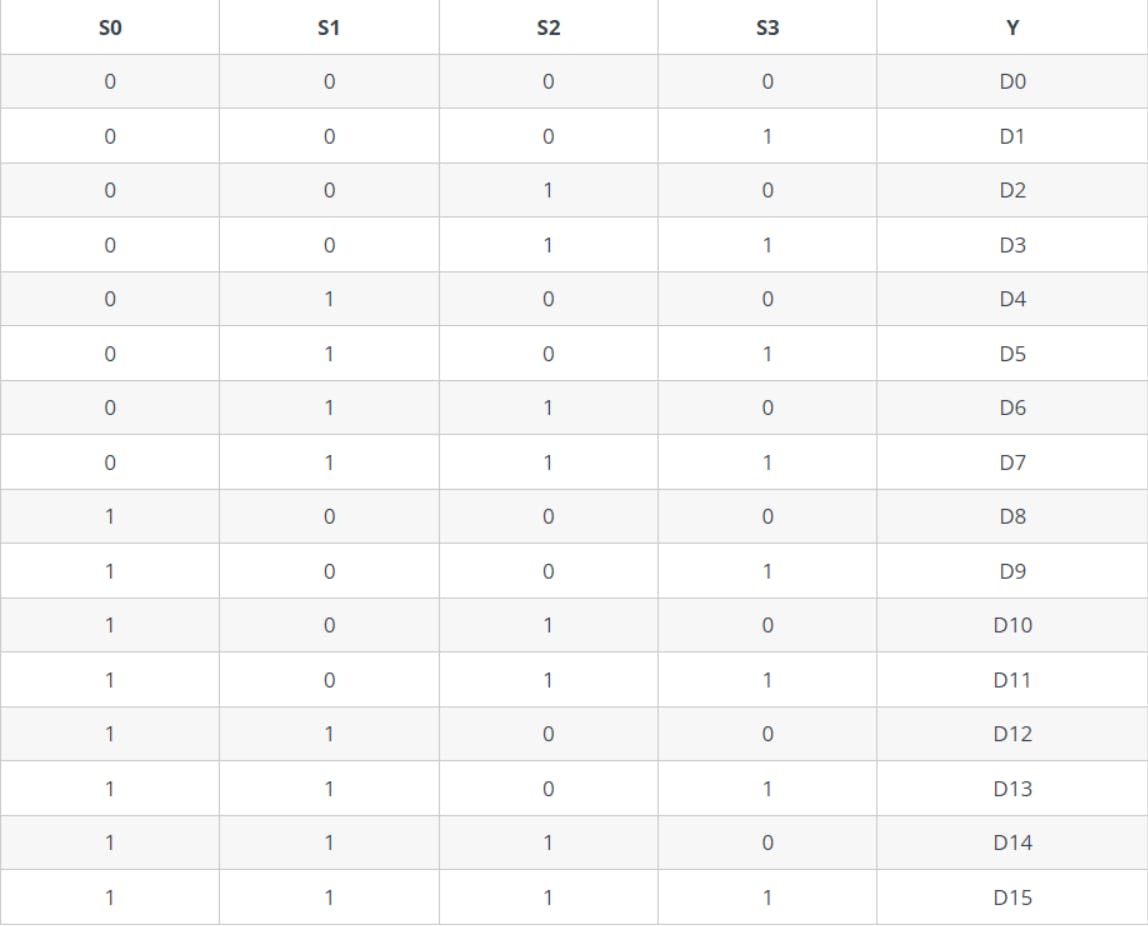
🟢16-to-1 Multiplexer
🔹Lower-order multiplexers can be used to implement all higher-order multiplexers such as 8-to-1, 16-to-1, and so on. However, let us take a quick look at the 16-to-1 Multiplexer.

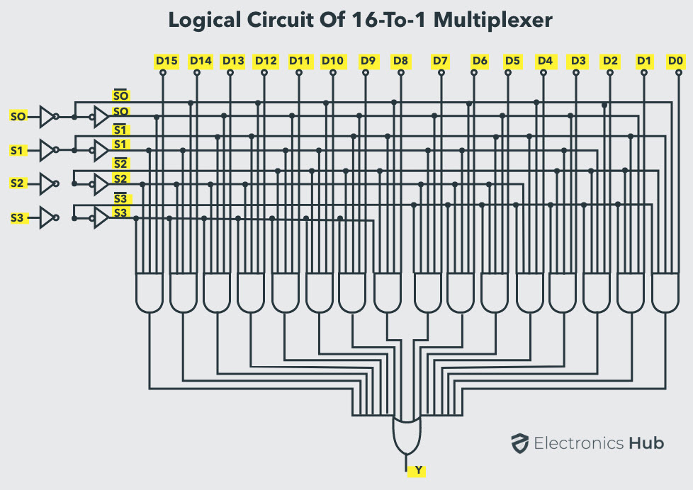
🔹The simplified truth table for the 16×1 Multiplexer is shown in the following table.
🔹The following image shows the logical circuit of a 16-to-1 Multiplexer. Well, Let me warn you, these circuits are for trained professionals... 😅
🔹We may create a 16-to-1 Multiplexer similar to an 8-to-1 Multiplexer by employing lower-order multiplexers such as 8-to-1, 4-to-1, and 2-to-1. The block diagram of a 16-to-1 Multiplexer implemented with two 8-to-1 Multiplexers and one 2-to-1 Multiplexer is shown below.
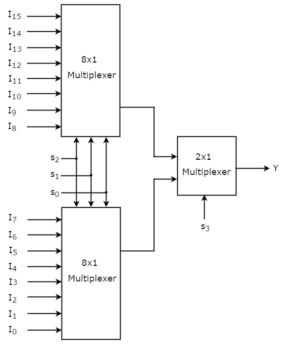
🔹Further, we can implement the individual 8-to-1 Multiplexers in the above image using two 4-to-1 Multiplexers and one 2-to-1 Multiplexer.
🟢Application of Multiplexer
🔹Multiplexers are widely used in all types of digital system applications.
🔹Multiplexers are used in a number of applications such as data routing, logic function generators, control sequencers, parallel-to-serial converters, and so on because they allow several inputs to be connected independently to a single output.
➡Data Routing
➡Logic Function Generator
➡Parallel to Serial Conversion
Thank you So much for reading😊. Hope I could add some value.
Written with heart by - MITHIN DEV
All representations belong to respective creators.