DE-MULTIPLEXER IN DIGITAL LOGIC? It's Easy If You Do It Smart
What is a Demultiplexer (De-mux)?

I'm a Tech passionate who is in the chase of awesome projects and interesting tech concepts. I wish to create an impact in the field of computer science.
🟢Introduction
🔹Multiplexers are straightforward combinational logic circuits that pick one of the multiple inputs and route it through a single output. Multiplexing is handled via the MUX device.
🔹A Demultiplexer's behaviour or function is diametrically opposed to that of a Multiplexer. Demux is a one-to-many circuit that is the inverse of the MUX. Data from one input can be sent to one of the numerous output data lines using a Demultiplexer.
🟢What is a Demultiplexer?
🔹Demultiplexing is the process of taking information from one input and transferring it to one of many outputs. If you recall, we examined the concept of multiplexing in the Multiplexer tutorial. Demultiplexing is the inverse of that.
🔹A Demultiplexer is a combinational logic circuit that accepts data on a single input line and transmits it over one of 'n' possible output lines.
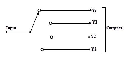
🔹To pick a specific output, we must utilise a set of Select Lines, and the bit combinations of these select lines govern which output line is connected to the input at any given time. The diagram below depicts the basic concept of a demultiplexer, in which the input is switched to any one of the four outputs is possible at a given instant.
🔹If Multiplexers are Data Selectors, Demultiplexers are Data Distributors since they send the same data that was received at the input to several destinations.
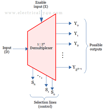
🔹Demultiplexers are thus 1-to-N devices, whereas multiplexers are N-to-1 devices. The graphic below depicts the block diagram of a demultiplexer, also known as a DEMUX.
🔹It has one input line, n output lines, and m select lines. In this case, m select lines are necessary to generate 2m possible output lines (given that 2m = n). A 1-to-4 demultiplexer, for example, requires 2 (22 = 4) select lines to control the 4 output lines.
🔹There are several types of demultiplexers based on the output configurations such as 1:2, 1:4, 1:8 and 1:16.
🔵1-to-2 Demultiplexer
🔹One input line, two output lines, and one select line comprise a 1-to-2 demultiplexer. The select line signal helps in switching the input to one of the two outputs. The block diagram of a 1-to-2 demultiplexer with an additional enable input is shown below.
🔹Because there are only two methods to link the input and output lines in the diagram, only one selection signal is required to perform the demultiplexing operation. If the selection signal input is LOW, the input is routed to Y0; if the selection signal input is HIGH, the input is routed to Y1.
🔹The truth table of a 1-to-2 demultiplexer

🔹Assume S is the Select Input, D is the Data Input and Y0 and Y1 are the outputs of the 1-to-2 Demultiplexer. From the above table, the output Y0 is active when the combination of the selection line and input line is active at low and high respectively, i.e., S D = 0 1
🔹Therefore, the expression for output Y0 is
Y0 = S' D
🔹Similarly, the output Y1 is active when the combination of the selection line and input line is active high, i.e., S D = 1 1
🔹Therefore, the expression for output Y0 is
Y1 = S D
🔵1-to-4 Demultiplexer
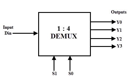
🔹A single input (D), two selection lines (S1 and S0), and four outputs comprise a 1-to-4 demultiplexer (Y0 to Y3). For a specific combination of select lines, the input data is routed to any of the four outputs at any given time.
🔹The truth table of this type of demultiplexer is given below. From the truth table it is clear that when S0 = 0 and S1 = 0, the data input is connected to output Y0 and when S0 = 0 and s1=1, the data input is connected to output Y1.

Y0 = S1' S0' D
Y1 = S1' S0 D
Y2 = S1 S0' D
Y3 = S1 S0 D
🔹Where D is the input data, Y0 to Y3 are output lines and S0 & S1 are select lines.
🔵1-to-8 Demultiplexer
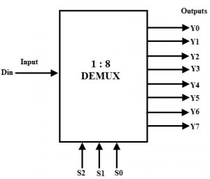
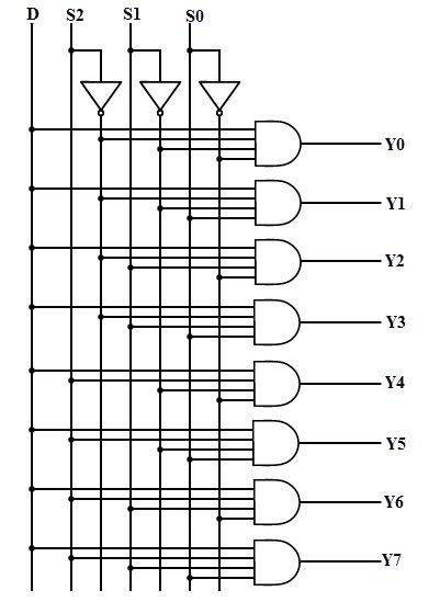
🔹The block diagram below depicts a 1-to-8 demultiplexer with a single input D, three select inputs S2, S1, and S0, and eight outputs Y0 to Y7.
🔹Because of its three select input lines and eight output lines, it is also known as a 3-to-8 demultiplexer. Depending on the mix of select inputs, it distributes one input line to one of eight output lines.
🔹The truth table for 1-to-8 demultiplexer is shown below. The input ‘D’ is connected with one of the eight outputs from Y0 to Y7 based on the select lines S2, S1 and S0.

Y0 = S2' S1' S0' D
Y1 = S2' S1' S0 D
Y2 = S2' S1 S0' D
Y3 = S2' S1 S0 D
Y4 = S2 S1' S0' D
Y5 = S2 S1' S0 D
Y6 = S2 S1 S0' D
Y7 = S2 S1 S0 D
🔹From these obtained equations, the logic diagram of this demultiplexer can be implemented by using eight 4-input AND gates and three NOT gates.
🔵1-to-8 DEMUX using Two 1-to- 4 Demultiplexers
🔹When the application necessitates a higher-order demultiplexer with a greater number of output pins, a single integrated circuit cannot be used. If more than 16 output pins are required, two or more demultiplexer ICs are cascaded to meet the requirement.
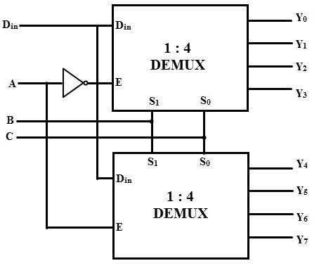
🔹when A is set to zero, one of the output lines from Y0 to Y3 is selected based on the combination of select lines B and C. Similarly, when A is set to one, based on the select lines one of the output lines from Y4 to Y7 will be selected.
🔵Implementation of Full Subtractor Using 1-to-8 DE-MUX
🔹Demultiplexers, like multiplexers, are utilised for Boolean function implementation and combinational circuit design. By appropriately manipulating the select lines, we may create a demultiplexer to produce any truth table output.

From the above table, the full subtractor output D can be written as
D = A' B' BIN + A' B B'IN + A B' B'IN + A B BIN
And the borrow output can be expressed as
BOUT = A' B' BIN + A' B B'IN + A' B BIN + A B BIN
From these Boolean expressions, a demultiplexer for producing full subtractor output can be built by properly configuring the 1-to-8 DEMUX.

🟢Applications of Demultiplexer
Demultiplexers are used in microprocessors or computer control systems.
Selecting different IO devices for data transfer (Data Routing)
Choosing different banks of memory (Memory Decoding)
Depending on the address, enabling different rows of memory chips
Enabling different functional units.
Thank you So much for reading😊. Hope I could add some value.
Written with heart by - MITHIN DEV
All representations belong to respective creators.
![[01] What is a Simple Game Engine?](/_next/image?url=https%3A%2F%2Fcdn.hashnode.com%2Fres%2Fhashnode%2Fimage%2Fupload%2Fv1679619224671%2Fde6bc474-4a14-4274-968b-6e3dc4d8e4e1.jpeg&w=3840&q=75)


